|
Home
Low Cost Road Construction in Ethiopia
Alem Ketema Sekota New Road Construction
Introduction
Under exploited resources, inappropriate economic policies and decades of disorder and civil war have resulted in Ethiopia being one of the poorest countries in the world. The 30-year civil war ended in 1991 but famine and starvation continue to be part of everyday life.
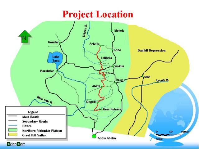
The Alem Ketema to Sekota Road Project was a new 675-km gravel road, which provides access to remote, drought prone areas of northern Ethiopia. This paper reports on the project and describes problem encountered and suggests some of the solution to these problems.
Background to the Alem Ketema to Sekota Project
Virtually all construction work over the past 20 years had been undertaken government owned companies, therefore little experience existed within the country for competitive tendering. As a catalyst to achieve their aim of stimulating a local construction industry the Government chose to construct several low cost rural road projects which would provide access into the remote northern areas of Ethiopia. Alem Ketema to Sekota is one of these roads.
The road is a basic standard all weather road, 6 meters wide and has a gravel surface. It shows a farsighted policy when you consider that this was initially a locally funded project and the Government was prepared to appoint an International Consultant to supervise the work. Later, agreements were reached with USAID and the project became indirectly funded by them.
To ensure speed of construction, the project was let as design and construct (turnkey) contracts to be paid on a lump sum basis. It was divided into five separate contracts.
Proposals were invited from Ethiopian contractors to prepare proposals and cost estimates. Assessments were made, contractors chosen and awards given to a selection of state owned and new private Ethiopia construction companies. Prices varied from between �27,000 per kilometre to �45,000 per kilometre. This includes the cost of bridges.
Project Aims
The aims of the project were to:
� provide all weather access to remote areas of Ethiopia, which are frequently subject to famine;
� To promote a viable domestic contracting industry;
� To introduce new methods of construction appropriate to circumstances found in Ethiopia.
Project Description
The Alem Ketema to Sekota project consists of five individual contracts, which provide a new continuous road between the towns of Alem Ketema and Sekota. The supervision of these contracts was awarded to Roughton International in late 1993.
The total length of road to be constructed amounts to 675 kilometers and passes through mountainous terrain in the central highlands of Ethiopia. It passes in a north south direction parallel to, and west of, the main road north form Addis Ababa, the capital, to Asmara in Eritrea and the Red Sea.
The standard of road is described as RR50 (Rural Road maximum of 50 vehicles per day). The road consists of a 6-metre wide gravel surface. All bridges are to have two lanes. Vertical gradients are kept below 12% and the horizontal curvature is limited to 30 metres radius except at switchback curves. The road is an "all weather road" therefore drifts or fords are not incorporated.
The area through which the new road passes had been the scene of some harrowing times in the mid 1970s and 1984/1985 famine. Any access into this area is extremely difficult and the distribution of food aid is a major problem. The new road provides communication for remote villages, giving basic health care and access to socio-economic facilities to many people for the first time.
The new road also provides an alternative route to the north passing directly through the remote centre of the country. It passes historic places such as Magdela and Lalibela. It is estimated that the new road will directly affect 2,000,000 people.
The 1984/85 Famine
The ability to distribute food aid is a major problem.
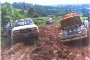
Ethiopia has one of the lowest density road networks in Africa. There is only 21 km per thousand square km and 0.4 km per thousand population. The majority of roads are unpaved and it is estimated that two thirds are impassible during the wet season. The majority of the 1.2 million people estimated to have died in the 1984/85 famine, did so after the aid agencies offered assistance.
In this area agriculture is extremely sensitive to variations in weather pattern. If global warming affects weather then natural disasters, famine and drought are certain to continue in the future.
Geography
 The Northern Ethiopian plateau consists of flat topped mountains or plateaux up to 4,000 metres which are intersected by river valleys orientated, generally, east to west. The plateaux are typically about 3,000 metres and the valley floors are around 1,800 metres in altitude. The new road crosses five of these major valleys. The scenery is reminiscent of the Grand Canyon is the USA. The Northern Ethiopian plateau consists of flat topped mountains or plateaux up to 4,000 metres which are intersected by river valleys orientated, generally, east to west. The plateaux are typically about 3,000 metres and the valley floors are around 1,800 metres in altitude. The new road crosses five of these major valleys. The scenery is reminiscent of the Grand Canyon is the USA.
The Contract Documents
The Ethiopian Roads Authority prepared the Contracts. They consisted of the following:
� Conditions of Contract;
� The Specification;
� Route Location Map at 1:250,000 Scale;
� List of towns and villages through which the road must pass;
� The Design Standards for RR50 roads.
The Standard Conditions of Contract and Specification were prepared in 1965 but had never been used to a great extent in a commercial environment.
The route location map was at a scale 1:250,000 with contour intervals at 50 meters.
The list of towns and villages through which the road must pass was extremely vague. Most of the named towns consisted of remote habitations constructed of mud huts called Tukuls. These villages were frequently dismantled and moved several kilometres from their original position, which frequently led to considerable confusion when administering the contract.
The design standards were defined in the Contract in a very rudimentary fashion. RR50 standard roads have been constructed in Ethiopia for many years by direct labour organisations but few roads, if any, have been constructed by contract. The design standards were defined with direct labour projects in mind. It is not surprising therefore, that certain many details were incomplete.
Many problems existed with the RR50 Design Standards. New bridges were to be constructed of two lanes but no mention was made of the actual width. The gravel-wearing course was specified at 150 mm thick, regardless of the subgrade strength.
These difficult contract issues were solved by preparing a comprehensive document which was titled "Design Standard Guidelines". All matters regarding design, such as allowable subgrade strengths to acceptable culvert outlet discharge velocities were specified. This allowed the contractors to design the road to an acceptable standard and clarified the contract.
There is scarcity of technical written material in Ethiopia. Any publication is gladly accepted and becomes authoritative.
Impact of the Road
Environmental impact assessments were not part or the consultancy brief. It is important, however, to consider the effects that the new road will have on the environment.
The World Bank Report "Kingdom Of Morocco Impact Evaluation Report-Socioeconomic Influence of Rural Roads " provides a likely scenario;
� Direct impact on transport infrastructure and services
- Open all year round;
- Vehicle operating costs reduced;
- Public transport fares will reduce;
- More efficient freight i.e. larger trucks;
- Road passenger increases;
- Access time to local markets falls dramatically.
� Impact on agricultural economy
- Land values increase;
- Change in crops with higher yield with higher profits;
- Increase in fertilizer use.
� Impact on social services
- Increase in primary education;
- Increase in use of health facilities;
- Increase in health quality;
- Easier access to potable water
� Impact on environment
- Curtailment of extensive goat and sheep herding;
- Increase in tree planting;
- Reduction in use of manure for burning;
- Air and noise pollution;
- Increase in fertilizer contamination;
- Localised construction soil erosion.
Geology
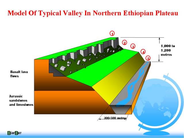
The project road traverse an area referred to as the Northern Ethiopian Plateau. This plateau is situated to the west of the Danakil Depression of the Ethiopian rift. To assist in assessment of alternative routes, different zones as shown on this typical model identified the terrain.
Terrain Zone Terrain Characteristics
1 High altitude plateau (3,000 � 4,000m) formed by near horizontal basalt lava flows. Either widely fractured basalt exposed at the surface or widespread cover of expansive black cotton clay soils. Sources of "as dug" gravel wearing course available but tend to be very coarse.
2 Near vertical rock face, frequent columnar jointed, with associated debris slopes. Debris typically comprising coarse talus and boulders with some fines. Blasting frequently required to form road bench. Landslide hazards include rockfalls, wedge and toppling failures at rock faces. Debris slides and rotational failures frequent debris slopes.
3 Lava flow terrace with colluvial cover on slopes and black cotton soils on flat areas.
4 Active lower valley slopes. Topography dominated by steep valley and gully side slopes covered with mantle of colluvial soil overlaying weathered bedrock. May be formed of basalt or older (Jurassic) sandstones and limestones.
5 Valley floors. Mainly coarse alluvial materials in river bed, terrace and fan deposits. Large river beds are often very active, with sediment deposition or erosion changing bed levels by several metres in a very short time during the wet season.
Design
Aerial photography is available at a scale of 1:50,000 scale. This is sufficient for route location work but has little or no use at the detailed design stage. Aerial photography at 1:5,000 is required for detailed design. This is not available. Inaccuracies in assessment of catchment areas led to many culvert failures.
Plan and profile drawing are produced at a scale of 1:2,000. Topographical maps are available at 1:250,000 and have contour intervals at 50 meters. These maps are not accurate enough for desktop studies although they were used because of a lack of an alternative.
The designers tended to emphasize horizontal alignment design and paid little attention to vertical alignment, drainage and pavement design. On this standard of road the vertical alignment constraints are considerably more important than horizontal alignment. Drainage and pavement design are also extremely important yet the majority of design input concentrates on the less important horizontal alignment.
Widening of the carriageway is recommended in the Guidance Notes for tight curves, high embankments etc.
Ridge top route are always favoured where available because of the lack or reduction in drainage facilities.
The Design and construct approach should enable easy of direct contact between design and contractor. This was not appreciated by the contractors who, tested to sub contract their design work to Addis Ababa based designer.
Materials
Gravel Wearing Course
The specification calls for a material which is generally pit run. No processing is generally required. Maximum particle size is 75 mm, plasticity index of between 9 and 15% and a Los Angles Abrasion test of not greater than 50%. The grading envelope is wide otherwise it would be difficult to produce this material.
 Weathered basalt is, almost without exception, the only source of material for wearing course. It tends to be found in zone 2,3 and upper parts of zone 4. The shortage of material in Zone 1 can lead to long haulage. Weathered basalt is, almost without exception, the only source of material for wearing course. It tends to be found in zone 2,3 and upper parts of zone 4. The shortage of material in Zone 1 can lead to long haulage.
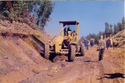
A more likely scenario is that the material is short of fines or has oversize material. Ethiopian contractors are most reluctant to use screens of any type. On one project a grizzly was constructed from 30 mm mild steel reinforcing bars "reinforced" with eucalyptus poles. The more general way is to transport the material, oversize included, to the site and then hand pick the oversize as the material is being laid. The amount of oversize is frequently 20% or more, therefore an uneconomical method of working.
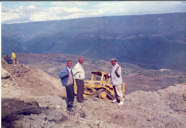
Contractor BERTA in despair as Bulldozer almost falls 1000 metres into the Jitta Valley
Other methods of breaking down the material before it leaves the pit were considered.
One methode is to break out the material with the dozer blade rather than using the ripper. This has the effect of slicing the material into smaller particles and proved to be effective. Another technique was to use the roller in the pit before the material was removed. It is considered that the roller is more effective at breaking down material when it has a solid rock support. Lots of people with large hammers has also proved to be effective, economic and practical.
Scouria � or volcanic cinder gravels are reported to be extensive in Ethiopia. None were found in the project area of exploitable quantities.
Masonry
Tuff consists of rock formed from volcanic ash. This type of rock is frequently too soft to be used as masonry stone.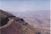 However, several quarries have been discovered where the material has sufficient hardness. This material is ideal for masonry. It is easily shaped and comes in several different and attractive colours. However, several quarries have been discovered where the material has sufficient hardness. This material is ideal for masonry. It is easily shaped and comes in several different and attractive colours.
Basalt- is extremely hard and difficult to shape. The common Ethiopian practice is to used rounded boulders from the river. Much effort is then needed shape into suitable masonry. When blasted from quarries, this material is more angular and produces superior masonry stone.
Frequently, the solution was to employ basalt at the lower levels in the piers and abutments where scour may be problematic. The more attractive tuff could then be used at a higher level above the scour level.
Aggregates
River gravels-are not normally used for concrete aggregate. The Ethiopian Specification does not prohibit their use but the general belief is that rounded aggregates are inferior to angular crushed aggregates.
One of the financially hard pressed contractors could not acquire a crushing plant. It was suggested that river gravels could be used as an alternative. Tests revealed that not only was the concrete of sufficient strength but they could reduce the cement content by a considerable amount due to the reduction in surface area of the aggregate.
The main problem with river gravels are that some sources have a high incidence of soft material. However, if care is taken over the source of material river gravels produce a strong, workable concrete ideal for most structural use and major savings can be realised by their use.
Crushed Basalt- is the more usual choice for aggregate. This is a fine grained rock and when crushed, produces an elongated, flaky material.
Black Cotton Soil
Black clay soils, known locally as black cotton, have formed over the basaltic volcanic rocks. They are found in areas with poor drainage; that is zone 3 and zone 1 in the terrain model. These black cotton soils are extremely expansive with high plasticity. Expansion pressures are high and bearing capacities are high when the material is dry and extremely low when the material is wet.
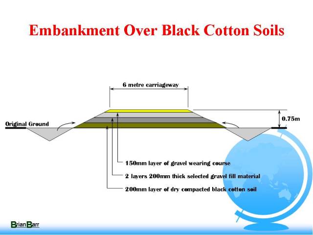
It was accepted that some expansion would be allowed during the wet season. The design solution is to construct an embank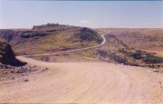 ment which provides good drainage to the embankment material, good drainage to the road surface, and counteracts the expansion pressures of the expansive material. Fiscal shows how this embankment was formed. 200 mm of dry compacted black cotton soil formed from the adjacent ditch, followed by 2 layers of 200 mm thick selected gravel material and capped with 150 mm gravel wearing course. This gives a total embankment height of 750 mm. ment which provides good drainage to the embankment material, good drainage to the road surface, and counteracts the expansion pressures of the expansive material. Fiscal shows how this embankment was formed. 200 mm of dry compacted black cotton soil formed from the adjacent ditch, followed by 2 layers of 200 mm thick selected gravel material and capped with 150 mm gravel wearing course. This gives a total embankment height of 750 mm.
Several embankments were monitored before and during the wet season and it was discovered that upward movements in the road surface were measured up to 20 mm. On a gravel road this is considered to be acceptable, but on a bitumen surfaced road it is acceptable and consideration should be given to an increased embankment height.
Drainage
Hydrology
Accurate rainfall data is very difficult to acquire. Much of the hydrologic calculations are therefore carried out by rule of thumb and empirical methods. What is most obvious is that the runoff from these mountainous areas is extremely high. Flash floods are common.
Cross Culvert in Narrow Gullies
In zone 2 and 4 slopes the road alignment must pass parallel to the cross slope. The alignment is determined by this slope but of course these slope are frequently incised by gullies. These gullies tend to be narrow and would not affect the horizontal alignment. However, it does mean that the road at this location, must be constructed on embankment 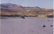 at the same location where it is wished to place a culvert. at the same location where it is wished to place a culvert.
This first ideas is the one most commonly used in Ethiopia and it is a satisfactory solution in areas where hard rock is exposed in the bed of the gully. If the gully bottom is erodible then it is not acceptable as the outlet velocity will be too destructive and possibly undermine the foundation of the wall.
One solution would be to turn the retaining wall round and makes teps in the front face. The same amount of masonry is used and the steps should act as cascade slowing the outlet velocity. This will work, but only in cases of low flow. At high flow the steps will, for all hydraulic purposes, be non existent.
A further solution is to slope the pipe down at the same slope of the gully. This produces very high outlet velocities which have to be contained by a stilling basin. The pipe also needs to be surrounded in concrete to cope with these excessive hydraulic forces. Not a particularly good ideas but one which will work given good design and workmanship.
Another solution is to keep the culvert near level and then construct a masonry cascade down the slope. The velocity of water is controlled at all times and is not allowed to become excessive. Local contractors worry about the settlement of this embankment and usually refuse the construct it. This embankment can be constructed of ripped rock fill. Not necessarily blasted material, just material with a predominance of rock particles of which there is an abundance. This will from a good stable embankment on which to construct a cascade.
However, we are only considering this problem in to dimensions. In most cases the gully is extremely narrow. The most satisfactory solution is to construct the culvert to a skew and the form a cascade down the side of the gully. This means that both the culvert and the cascade are constructed in stable original ground.
Lined Ditches
Lined ditches are constructed by mortared masonry. They are expensive in the use of cement. The stone is laid flat on the natural ground and mortar is introduced in the gaps. The problem with this is that the size of the ditch is not calculated and the Ethiopians standard ditch is only 50 mm deep. Obviously insufficient for more than minimal flows. To overcome this problem simple calculation sheets were introduced from which the size of the ditch can be calculated using the Manning formulae. This has led to, in the contractors opinion, a large uneconomical ditch. However, during the first wet season many standard sized ditches were destroyed due to overtopping and resultant scour.
A solution which was suggested use dry stone lining to the ditch with a minimum 400 mm long stone set on end with the long axis perpendicular to the ground. Smaller stones can be wedged into the cracks.
A trial section was constructed and costed by the contractor. Unfortunately the contractor chose a location where stones of suitable size were not available. The costing therefore proved too high. This form of construction may prove to be economical in the long term and contractors should be encouraged in its use.
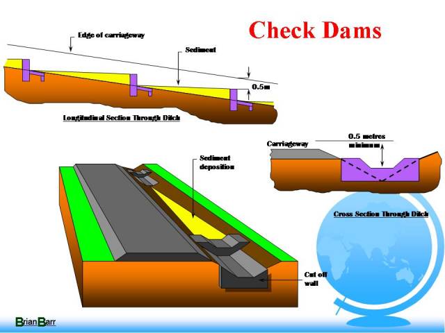
Check Dams
Check dams are a method of preventing ditch erosion that is commonly employed and used in Ethiopia.
They are effective if the check dams are constructed properly. The spacing is critical and also the shape must be correct. Check dams have been redesigned because the Ethiopian standard design was found to be inadequate. The main points are that the top of the weir must be well below the road level otherwise water flows over onto the road and erodes the gravel wearing course. Another problem is that the side walls must extend above the flow of water over the weir to ensure that erosion does not occur behind the side wall. A cut off wall should always be provided and all excavations should be back filled with the abundant supply or rocks.
Slope Stability
Gabion Baskets
Gabion baskets have been considered for retaining walls, revetments and other drainage structures. There is a plentiful supply of rocks of suitable size and shape and these flexible structures are ideal for mountainous terrain. There are problems however.
With shortage of foreign currency they are difficult to purchase. This problem can be overcome by manufacturing them on site using local labour and locally produced galvanized wire.
The second problem is not so easily solved. The local population through which this road passes have absolutely nothing. Wire is clearly a valuable commodity and even short lengths would be found useful. This worry is borne out by the fact that the local population frequently break up the reinforced concrete pipes to get the steel reinforcement. When concrete pipes are delivered to site awaiting installation, the contractor must set up a guard to protect them.
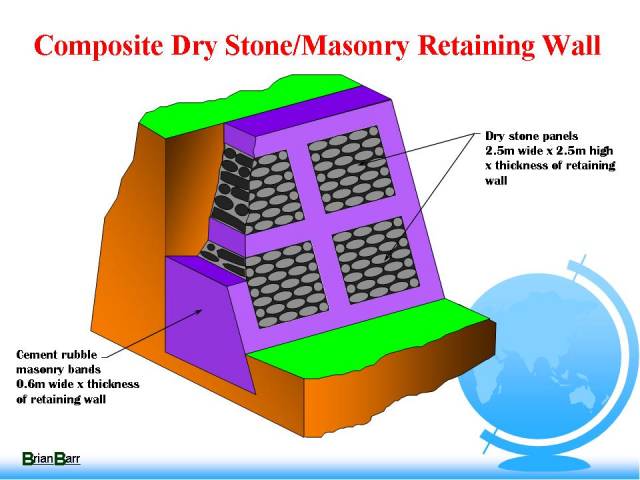
Composite Dry Stone/Masonry Retaining Walls and Revetments
Composite masonry walls and revetments are similar to mortared masonry walls and revetments except that they have panels of dry masonry. These panels form a grid on the face with 0.5 metre mortared division strips. They are stronger than dry masonry and, at the same time, maintain the advantage of relatively free drainage. Where concern is expressed by the Contractors about the cost of cement, these structures are a good alternative to masonry structures.
Bridges
The traditional Ethiopian bridge is constructed of reinforced concrete (Reinforced concrete Deck Girder RCDG). It utilizes 5 beams and has a maximum span 25 metres. It is simply supported and has mild steel reinforcement. The construction is always insitu, using eucalyptus poles to construct the falsework. No engineering desin is used for this flsework and its construction is left in the hands of the foremen. The design is about 30 years old and uses a standard drawing. If the bridge isn�t long enough then more spans are used. The use of mild steel means that many layers of steel in the bottom of the beam are needed the upper layers of steel are as a consequence under stressed and the whole design is extremely clumsy.
The introduction of high yield steel was only satisfactorily introduced on one contract where the Contractor had over 35 bridges to construct. He was able to estimate the amount of steel he would require and has the time to import Kenya. Significant saving were achieved.
Further improvements were made to the bridge designs by increasing the depth of beam and thereby reducing the number of beams from 5 to 3. Also continuous spans were introduced.
Falsework
One of the main problems with this type of insitu bridge construction is the fact that lots of timber is required in the falsework. No design for this falsework is usually carried out. The actual layout is determined by the foreman. This can be reduced by designing the falsework and producing drawings which the erectors must follow.
Jitta Bridge
The Jitta river is about 200 metres across and has one of the fastest estimated velocities of flow at 6 metres per second. The potential for scour failure here is extremely high. A bridge had been constructed at this location by the Italians during the second world war. It had failed during the first wet season and is hardly surprising. It had foundation 1,5 meters deep, it crosses the river at an acute skew angle with 12 metres spans and was also constructed immediately below the confluence of a major side river with large transportation of material. It was obviously going to be a steel composite structure although the concrete deck had never been added. There were many RSJ�s lying around and buried within the river bed.
The new bridge site is situated upstream above the point of confluence with that difficult side stream. Because of the potential for scour it was agreed that the foundations would be deep, 8.5 meters, and therefore would be difficult to build. Hence the fewer the better. A longer span was therefore proposed.
This particular contractor was not experienced in the construction of bridges but he did have lots of experience constructing concrete buildings. He could build concrete floors walls and roofs. Hence the idea to build a concrete box section seemed ideal. As there is plenty of gravel material lying in the river bed, and we have bull dozers aplenty to move material, why not build an embankment on which to construct the box section.
Incidentally, the masonry piers have had to be reinforced because of the flow forces of the river.
The foundations and piers have now been constructed but I was unable to reach the site to take any photographs. This photo shows the holes which were excavated to construct the foundation piles. It is not possible to take a carne or other large equipment to this site. We had envisaged the contractor using concrete pipes as caissons rather than digging these enormous holes by bull dozer . He had a difficult task trying to keep these excavations free from water and breakages of pumping equipment delayed the construction of this bridge.
Tekaze bridge
The Tekaze bridge is a major river system which flows directly into the White Nile in Sudan. The river is contained within a deep gorge which the flood waters overflow.
Any traditional bridge would involve extremely lengthy piers and would be a major constraint on the flow of water. Eucalyptus falsework would be extremely difficult to construct over the gorge. Many ideas were considered. In particular, the favoured method of construction involved precasting and launching techniques. One proposal included the launch of concrete beams using the jib of an old tower crane found in Addis Ababa. Another proposal involved the casting insitu from formwork supported by the tower crane jib.
In the event it was decided to use steel beams recovered from the failed Italian bridge at the Jitta river.
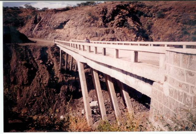
Konga Bridge
The falsework for this bridge has been structurally designed and hence a more economical use of timber has been achieved.
What is of particular interest of this bridge is the fact that the contractor used the design construct concept to his advantage. The bridge was to have a standard 25 meter span RCDG but after construction of the south abutment it was discovered that the north abutment foundation was extremely deep. The bos section for the Jitta bridge was being designed at the time so this concept was used here and the span increased to 35 meters thereby reducing considerably the size of the north abutment.
Ketchin Ababa Bridge
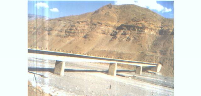
The largest mobile crane in the country is 45 tons capacity and it was possible to gain access to his bridge site. The idea for this bridge was to introduce a precast type construction. Because the units are cast on the ground the shape can be much more complex. Quality control is much better and the concrete work on this bridge is probably the best for the whole projects.
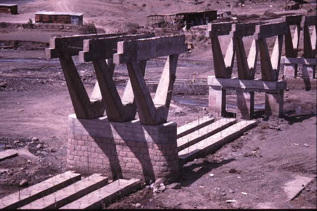
The 'Y' frame therefore were cast on the ground and then raised into position by one 45 ton crane and bolted down using engine bolts from caterpillar graders. The units are set on shims and eventually grouted with 5 star grout. The actual bending moments within the piers are taken by reinforced concrete piers which are encased in masonry.
By using this form of construction the maximum span is achieved for the lifting capacity of the cranes. It also produces an elegant bridge style unique in Ethiopia.
The bridge is close to the rock hewn churches constructed by King Lalibela in the 12th century and is of immense importance to Ethiopian Orthodox Christians and is a major tourist site. Masonry for the piers is the same color and type as that used in the churches. According to the contract, the modern concrete structure is seen to rise out of the traditional masonry structure.
Flow of Information
Necessary to create an awareness of ideas and developments. Training of large number of people, new concepts, skills and techniques.
This slide shows how information is passed around the site during the design and construction process. Drawings are prepared on the basis of the design submitted to the Engineer for approval, approved issued to the site, then ignored. The difficulties of transmitting ideas down to the work force are enormous and are experienced by contractors management and supervisor alike.
There are in excess of 3000 major and minor drainage structures being constructed by between 30 to 40 gangs of masons and labourers. They know how they have done this work in the past and this is what you will get. None of these people know or understand how to read drawings. The introduction of new ideas at a basic level is a particularly difficult problem.
Engineering drawings in Ethiopia frequently include an isometric perspective, even when it is a fairly simple concept. This idea was employed by producing three dimensional color drawings of culvert headwalls and other similar structures which were then distributed to work crews on the site.
One common problem that required a solution was the scour which always occurs at the back of culvert headwalls. Long periods of drought mean that all vegetation dies and sudden bursts of rain erode vulnerable places like the back of headwalls. The solution is simple, back fill with the abundant amounts of rock. Instructions to the contractor and supervisors never seemed to solve the problem.
Three dimensional drawing are now handed out to all workmen involved in head wall construction with successful results.
Conclusion
For more than 20 years the private sector in the construction industry has been stifled by an unfavorable political, economic and legal environment supported by a multitude of cumbersome bureaucratic regulations and procedures. Many changes, at all levels of Government are needed to change this situation.
The need for basic standard roads vital for the continuing existence of people in rural areas. They provide access for food aid, provide access to medical facilities and promote the agricultural activities for the good of all.
The design of construct rural road projects were conceived to promote three main objective i.e. situated a local contracting industry, provide access to remote rural areas and introduce appropriate construction technique. In this respect the programme has been successful. Although all the project are behind schedule, work is proceeding. Contractors are becoming more experienced in a commercial environment and the formation of a local constructing industry is being realized. Access is being provided into remote area and new appropriate techniques are being introduce.
Home |